Subsea Hot Tapping and Line Stopping
1. Introduction & Background
Subsea pipelines constitute integral components of all offshore oil and gas projects as they are considered the most economical, environment-friendly and safe means of petroleum transportation – multiphase fluids, crude, gas or petroleum products. Subsea pipelines (also called marine, submarine or offshore pipelines) transport multiphase flow (mix of oil, water, contaminants and gas) from subsea wells to the platform and after processing carries crude, condensate or gas from the offshore platform to the coast for onward distribution to refineries or consumption centers.
General Characteristics of Subsea Pipelines
Based on their utility, subsea pipelines are categorized as:
- Flow Lines or Feeder Lines: These are usually smaller diameter pipelines (6 5/8 – 12-inch dia line pipe) carrying multi-phase flow from subsea wells to a piping manifold at the offshore platform. There are instances where these lines also carry processed water from the offshore platform back to re-injection subsea wells for disposal. Some test flow lines, injection lines, or gas lift lines may be as small as 2-inch diameter.
- Offshore Platform Export Pipelines: These are usually medium diameter pipelines (mostly 12 – 30-inch diameter pipelines with few exceptions where 42-inch, or larger, diameter pipelines are used) which transport gas or oil from the offshore platform to coastal installations. In some cases, smaller, typically 6 – 8-inch diameter export pipelines (called offloading lines) are used for oil transfer from the offshore platform to ship tankers through mooring and offloading systems. Mostly these pipelines are single-phase (carrying either oil or gas), but some multiphase pipelines are also in operations.
- Long Distant Transport Pipelines: These are large diameter pipelines (usually above 30-inch diameter line pipe) used for long-distance petroleum transportation.
Subsea steel pipelines are designed for 10 – 40 years of service and need to be protected externally from corrosion. API 5L and DNV TS F101 standards are used for the design of subsea pipe. The most commonly used API grades for line pipe used in subsea applications are API 5L-X52, API 5L-X60, and API 5L-X65.
While transport / export pipelines usually are not prone to internal corrosion, flow lines and feeder lines carry multiphase flow, including water and contaminants, can sometimes cause internal corrosion. One method to avoid internal corrosion is to use corrosion-resistant alloy steel as line pipe material, which increases material and construction cost tremendously. Subsea pipelines are externally coated, and sometimes internally coated, to guard against corrosion, as described:
- Internal Pipe Coatings
Internal coatings provide corrosion protection and improve pre-commissioning activities, pipeline operations, and pigging operations due to smooth internal surface whereby increased efficiency is achieved by lowering the internal surface roughness. Epoxy-based materials are commonly used for internal coatings as they provide a smooth finish, sufficient hardness, water resistance, flexibility, chemical resistance and excellent adhesion.
- External Pipe Coatings
External coatings for subsea pipelines should provide resistance to seawater absorption, chemicals in seawater, weathering, impact / abrasion, high flowing temperatures and be compatible with cathodic protection (CP). 3-Layer polyethylene (PE) or polypropylene (PP) coatings provide external corrosion protection because of their high dielectric strength, water tightness, thickness, and very low CP current requirement. Also, concrete weight coatings are common for subsea pipelines to stabilize the pipeline on the seabed. Typical densities of concrete used to coat subsea pipelines are in the range of 140 lbs/ft3 and 190 lbs/ft3. Concrete density can be increased to 275 – 300 lbs/ft3 by adding iron ore.
Subsea Pipeline Construction
Subsea pipeline construction is usually based on three laying techniques:
- S lay – Pipeline is curved twice before laying on the seabed (typical for deep-sea laying)
- J lay – Pipeline is curved once before laying on the seabed (mostly used for deep-sea laying due to lower pipe stresses and lower installation tensions)
- Tow in – Pipe strings are welded onshore, and marine vessels are used to carry pipe strings to installation sites (typically limited to shallow water installations due to weather risks)
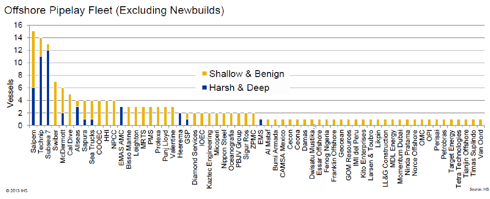
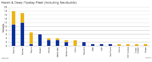
The following are two charts reproduced from HIS Markit data of subsea pipeline contractors in the order of fleet capability.


Subsea Pipeline Design Codes and Standards
DNV GL
DNV GL was created in 2013 through a merger of Det Norske Veritas (a Norway based free-standing, autonomous and independent foundation whose purpose is to safeguard life, property and the environment) and Germanischer Lloyd (a Germany based consulting and classification firm that deals mainly with maritime and energy industries). DGV GL is today an international accredited registrar / accredited certification body as well as the world’s largest Classification Society.
DNV-TS-F101 (previously DNV-OS-F101) Offshore Standard for Submarine Pipeline Systems provides acceptance criteria and design procedures for subsea pipelines. The standard applies modern limit-state-design principles with ‘safety classes’ linked to consequences of failure. The DNV GL standard is complemented by many recommended practices (RPs):
- DNV-RP-C205 Environmental Conditions and Environmental Loads
- DNV-RP-F101 Corroded Pipelines
- DNV-RP-F102 Pipeline Field Joint Coating and Field Repair of Linepipe Coating
- DNVGL-RP-F103 Cathodic protection of submarine pipelines
- DNV-RP-F105 Free-Spanning Pipelines
- DNV-RP-F106 Factory Applied External Pipeline Coatings for Corrosion Control
- DNV-RP-F107 Risk Assessment of Pipeline Protection
- DNV-RP-F108 Fracture Control for Pipeline Installation Methods Introducing Cyclic Plastic Strain
- DNV-RP-F109 On-bottom Stability Design of Submarine Pipelines
- DNV-RP-F110 Global Buckling of Submarine Pipelines
- DNV-RP-F111 Interference between Trawl Gear and Pipelines
- DNV-RP-F113 Pipeline Subsea Repair
- DNV-RP-F116 Integrity Management of Subsea Pipeline Systems
- DNVGL-RP-O501 Managing sand production and erosion
API Standards
- API SPEC 5L Specification for Line Pipe
- API RP 5LW Recommended Practice for Transportation of Line Pipe on Barges and Marine Vessels
- API RP 14E Recommended method for design and installation of offshore production platform piping systems
- API Std 521 Pressure Relieving and Depressuring systems
- API RP 1104 Welding of Pipelines and Related Facilities, STD
- API RP 1111 Design, Construction, Operation, and Maintenance of Offshore Hydrocarbon Pipelines
- API 579-1/ASME FFS-1 Fitness-For-Service
- API Recommended Practice 2A-WSD. Planning, Designing, and Constructing Fixed Offshore Platforms—Working Stress Design.
ASME Codes
- ASME B16.5 Pipe Flanges and Flanged Fittings
- ASME B31.3 Process Piping
- ASME B31.4 Pipeline Transportation Systems for Liquids and Slurries
- ASME B31.8 Gas Transmission and Distribution Piping Systems
- ASME B31.8S Managing System Integrity of Gas Pipelines
- ASME B31Q Pipeline Personnel Qualification
- ASME BPV Section V Nondestructive Examination
- ASME BPV Section VIII – Divisions 1 and 2, Pressure Vessels
- ASME BPV Section VIII Division 3 High-Pressure Vessels
- ASME BPV Section IX Welding and Brazing Qualifications
ISO Standard
- ISO 19345-2:2019 – Petroleum and natural gas industry — Pipeline transportation systems — Pipeline integrity management specification — Part 2: Full-life cycle integrity management for offshore pipeline
2. Subsea Pipeline Operations And Maintenance
Newly installed subsea pipelines are pressure tested as part of commissioning procedures. Today, most offshore pipeline contractors carry leak detection systems on-board the vessel to identify pipeline leakages and hydro-test failure scenarios. Hydrostatic testing procedures provide for raising the pipeline pressure in steps to see whether pressure holds for a defined time-period at each step-level. In case the static pressure holds until the operating pressure plus a safety margin, the pipeline is declared as not leaking. If the hydro-test fails at any test pressure, then there is a leak somewhere that has to be located and repaired.
The successful operation of subsea pipelines is dependent on a reliability-centered maintenance strategy. This is essential to keep hydrocarbons flowing smoothly from seafloor wells to processing sites and consumption centers. Leak or flow interruption needs to be detected immediately as it occurs. Subsea leak detection / flow interruption is identified through changes in operational parameters. Upon completion of pipeline repairs, the leak detection system must be re-deployed to confirm that the repairs are successful. Various leak detection methods are used, such as:
- Fluorescent Detection – long-range fluorescence for control fluids or oil
- Acoustic Detection – passive acoustics
- Temperature Detection – differential temperature
- Methane (Vapor) Detection
- Hydrocarbon Detection
- Air bubbles
Different surveys and inspection devices can be deployed for inspection of subsea pipelines to ensure the reliability of operations. Inspection or survey devices include ROVs (Remotely Operated Vehicles), AUVs (Autonomous Underwater Vehicles) and Smart Pigs (In-line inspection pig). For shallow waters, diver inspectors are also commonly deployed for manual inspection of subsea pipelines.
Damages to subsea pipelines that cause metal loss line internal blockage or dent / crack require repairs wherein hot-tapping and (sometimes) line stopping operations get involved. Additionally, operational requirements involving changes in flow line configurations also lead to the use of hot-tapping and line stopping operations to be carried out on subsea pipelines.
3. Benefits Of Hot Tapping / Line Stopping Operations On Subsea Pipelines
Subsea hot tapping and line stopping has become a relatively common solution for adding a lateral to a pipeline, mitigating a pipeline blockage, or preparing a pipeline for abandonment.
In some cases, subsea pipelines have been designed to be prepared for future connections by incorporating pre-installed tee-assemblies. Some of these require hot tapping through a specially designed blind flange integral to the tie-in assembly that facilitates such a process. There are different technologies in use for implementing hot-taps and line stopping operations on subsea pipelines, including:
- Preinstalled welded tees
- Grouted Tees
- Mechanical Bolted Tees
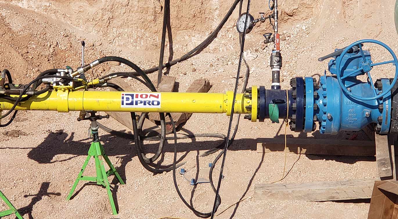
- Hot Tapping Machines
Subsea hot tapping operations provide lower-cost potential solutions for modification and repair of export pipelines, flow lines, feeder lines and long distant transport pipelines. Technological development has made available benefits of hot-tapping and line stopping for shallow, deep-water and ultra deep-water depth subsea pipelines. As such hot tapping and line stopping have extensive usage and associated benefits in maintenance of subsea pipelines:
- Globally, the environmental aspects of pipeline systems are of significant concern for the pipeline operators. Regulatory concerns govern that hydrocarbon leaks into the ocean must be avoided to prevent ecological and environmental damage or, in some cases, large scale disasters. Hot tapping and line stopping operations help companies in complying with such regulatory requirements.
- Making connections to host pipeline while the host pipeline remains in service
- Tie-ins to existing export pipelines. Several construction steps can be avoided during the construction of subsea pipelines like ship layout, horizontal interface docking arrangement, pipe retrieval, pipe cutting, pairing, welding and pig launching through hot tapping and line stopping technology.
- Reconfiguration of existing flowlines in line with field development and optimization program. Flowline and feeder line extensions can be added to the main pipeline while the pipeline remains in service, avoiding costly shutdowns and interrupting production operations.
- Plugging operations for pipeline or well abandonment
- Replacement of a damaged or blocked section of subsea pipeline or rerouting
- Live pipelines can be worked without worrying about product leakage or environmental hazards
- Non-uniform consolidated settlement of sandy seabed and sand erosion due to ocean currents put the free-spanning pipeline section under stress. Hot tapping is sometimes the only option available to reroute the pipeline to avoid damage.
4. Hazards Of Hot Tapping / Stopping Operations On Subsea Pipelines
Subsea pipeline operations are technically challenging due to harsh environmental conditions. Environmentally harsh conditions contribute to damage to subsea pipeline systems and make repair operations difficult. These pose severe hazards during complicated operations like hot tapping and line stopping. Hazards that need to be considered are broadly three types:
- Hazards due to human error
- Hazards due to environmental conditions
- Hazards due to equipment failure
Human Error
- Insufficient safety protection
- Lack of job qualification
- Poor operation capacity
- Poor motivation
- Improper command, supervision and communication
- Poor operation training
- Unreasonable personnel structure
- Improper operations planning
Environmental Conditions
- Low visibility in seawater
- Strong wind
- Strong ocean current
- Strong wave
- Deepwater effects on divers and robotic function and latency
Equipment Failure
- Draw-works failure
- Measurement equipment failure
- Power (hydraulic) equipment failure
- Instrumentation failure
- ROV (Remotely Operated Vehicle) failure
- ADS (Advanced Design System) failure
In addition to the above hazards, certain barriers are limiting the use of hot tapping and line stopping techniques for subsea pipeline repairs:
- Hot tapping and line stopping is generally implemented only on straight and accessible sections of the subsea pipeline.
- Subsea pipeline location and geometry need to be carefully considered, and provisions may be required to excavate hot pipe before the start of the operation.
- Hot tapping and line stopping procedures may not be implemented if there are issues with host pipeline integrity.
- Hot tapping has pressure and temperature limitations.
Minimizing Hazards of Hot Tapping / Line Stopping Operations
Subsea pipeline hot tapping and line stopping operations’ risk minimization can be achieved by focusing on the following three things:
- Suitable equipment and established procedures: Proper preparation of equipment with well-defined procedures and processes.
- Training of personnel and supervision: It is of paramount importance that the entire team of personnel deployed for hot tapping / lines stopping operation is trained and have experience to their credit. Undertaking regular reviews and training to ensure that the offshore team knows what they are doing.
- Detailed planning: Engineers should spend a significant amount of time on every small planning detail considering every eventuality – even failure and retrieval; it is a well-known saying about subsea pipeline maintenance, “one thing you can be sure of is that as soon as you attempt to undertake a simple process underwater, it will become complicated.”
