Pipeline Pitting and Repair Techniques
In this article, ION Pro explains that pipelines are the most cost-effective and environment-friendly mode of hydrocarbon fuel transportation. The focus of this paper is on the repair of pipeline defects that require repair/reinforcement against failure due to circumferential stresses.
1. Introduction and Background
Pipelines are the most cost-effective and environment-friendly mode of hydrocarbon fuel transportation, if and when operated under prudential industry practices or standards. Starting from wellheads, high-pressure steel pipelines handle multiphase fluids, slurry, crude, condensate, and raw natural gas.
While on the downstream side, they deliver petroleum products and pipeline quality gas to consumption points. This article discusses onshore pipelines, which constitute the overwhelming majority of world pipeline installations. The focus of this paper is on the repair of pipeline defects that require repair/reinforcement against failure due to circumferential stresses.
1.1 1.1 Major Causes of Pipeline Damage and Metal Loss
Before discussing pipeline repair techniques, it is imperative to highlight possible causes of pipeline integrity damage briefly. This know-how serves to benefit operators to take preventive actions before actual damage occurs to pipelines.
Bulk transport pipelines typically operate at high pressure and sometimes may also be subjected to high temperatures. Metal loss occurs over time due to interaction with transport fluid and environment. Downstream pipelines typically do not experience internal pitting or corrosion but are exposed to external corrosive environment as they are buried underground. Internal metal loss in downstream pipelines may occur due to erosive velocities achieved by flowing fluid under low-pressure conditions.
On the other hand, upstream pipelines (wellhead to gas processing plant or storage/refinery site) have a greater risk of internal corrosion as they often carry high temperatures produced fluids that contain corrosive substances like sulfur, mercaptans, organic acids, salts and acid gases – H2S, CO2.
Pipeline failures seldom occur under ordinarily applied engineering loads or stresses. The probability of pipeline failures increases significantly when engineering loads are amplified by residual stresses existing in the pipeline. These residual stresses get induced in the pipeline structure as a result of fabrication processes or environmental interaction.
Annealing or thermal stress relieving is not a practical option for pipelines, being dimensionally large assets. As such there are additional causes of mechanical damage to buried pipelines:
- Stress corrosion cracking (SCC)
- Sulfide Stress cracking (SSC)
- Corrosion fatigue
- Hydrogen induced cracking (HIC)
- Accidental digging (by heavy construction or farming equipment)
- Soil movements in geologically active areas.
2. Dealing with Pipeline Damage and Metal Loss
Pipeline lifecycle begins with ROW selection preceded by geotechnical investigations and bathymetric surveys through to designing, construction, welding, quality control, commissioning, operations and ends with maintenance of pipeline integrity. Pipeline operations are regulated activities throughout the world, and essential pipeline integrity considerations for operators are:
- Risk mitigation to avoid damage compensation and regulatory penalties
- Reduction in maintenance costs through prioritization of repairs
- Sustainable business operations that are socially and environmentally justified
2.1 Understanding and Quantifying Pipeline Damage / Metal Loss
Once a pipeline is commissioned and operational, the integrity measures are primarily a combination of predictive and preventive maintenance strategies. Both these strategies are implemented successfully through condition monitoring, validation of damages, and prudent choices of repair techniques for different pipeline damage types – external as well as internal metal loss or damage. Pipeline Integrity Management Software also supports operators’ decision making related to the prudent choice of repair technique.
Visual inspection, Inline inspection (ILI) using intelligent pigging and NDE through physical thickness testing provide the means for validation of threats to the integrity of in-service pipelines. A threat that has been validated to be a risk to pipeline integrity has to be eliminated or rectified.
2.2 Classification of Repair Techniques
Pipeline repairs are typically carried out under defined SOPs, but the variety of problems encountered by geographically-scattered pipeline networks do not often have fit-for-all standard solutions. Basic criteria for selection of a repair technique are rectification of damage at minimum cost as well as restoration of pipeline capability to designed operating conditions for remaining life, i.e., prevention of damage propagation resulting in a future catastrophe. Keeping basic criteria in mind, we can classify for repair techniques, based on the cost of repair, starting from least cost as:
1. In-service repair – for external damage or metal loss on pipelines
2. Isolated or off-service repair – for internal damage or metal loss on pipelines (also used for external damage or metal loss on pipelines when in-service repair is not possible)
In-service repairs are less costly as they do not require decommissioning of pipeline segment (including loss of hydrocarbons) and can be attempted with minimal disruption to normal pipeline operations. Isolated repairs are associated with high costs as they disrupt operations, cause unwanted releases of hydrocarbons, and take longer to implement. Pipeline segment replacement is also an option of last resort under off-service repair.
Visual inspection, Inline inspection (ILI) using intelligent pigging and NDE through physical thickness testing provide the means for validation of threats to the integrity of in-service pipelines. A threat that has been validated to be a risk to pipeline integrity has to be eliminated or rectified.
3. In-Service Pipeline Repair Techniques
In-service repair techniques are deployed as per requirement analysis related to operational constraints, pipeline configuration, geographical location, and severity of damage to the pipeline as identified below:
- Minor damage on the pipeline surface.
- Significant damage to the pipeline surface, where leakage or spill has not initiated.
- Significant damage to the pipeline surface, where leakage or spill has initiated.
In-service pipeline repair techniques may or may not require welding. In-service pipeline welding, where involved, should not be attempted by personnel who are lacking sufficient knowledge, experience, and expertise needed under relevant codes, recommended practices, or standards developed for safe work execution.
This is because the wrong execution of welding jeopardizes the safety of worksite and may severely compromise the integrity of the pipeline due to burn-through or material degradation. The reader is advised to consult following to acquire adequate knowledge:
- ASME B 31.8
- ASME B 31.4
- ASME B 31.3
- API 1104
- Relevant OSHA guidelines
3.1 Grinding
Minor damages, welding anomalies, or line pipe metallurgical discontinuities can be removed through grinding, thus eliminating the possibility of crack initiation. Additionally, grinding is used to remove stress concentrations due to the presence of extremely hard or relatively softer metal in completed pipelines.
Codes/standards do not provide any limitation on the length of grinding span when it is used to remove metal that is < 10% of designed pipe wall thickness. Grinding should not be used to remove metal more than 40% of designed pipe wall thickness. Die penetrant method, or magnetic flux can be used to check for soundness of repair. If required (when remaining pipe wall thickness is less than minimum allowable wall thickness), the metal loss can be re-deposited through a weld patch, or a composite wrap can reinforce that portion. [/et_pb_text][et_pb_text _builder_version=»4.4.1″ global_colors_info=»{}» theme_builder_area=»post_content»]
3.2 Weld Overlay / Weld Deposition Repair
Weld overlay is a pipeline repair technique where a suitable metal is deposited through welding to the pipe surface, valve body/trim, or a pipe fitting in the form of a layer. This may be used to improve pipe strength or surface protection while keeping the base structure’s strength, e.g., as a guard against corrosion.
Weld overlay provides layering of an alloy metal different in material from that of base pipelines and associated piping/fittings. Weld overlay is carried out by shielded metal arc welding, Metal Inert Gas (MIG) welding/Tungsten Inert Gas (TIG) welding, Submerged arc welding, CO2 welding or Plasma Transferred Arc (PTA) welding.
Weld deposition is best suited for difficult or complicated pipe configurations or contouring pipelines. Weld deposition, in some instances, provide better corrosion and wear resistance than sleeves with regards to galvanic corrosion. Weld deposition is also a proper repair technique to inhibit crevice corrosion and fretting corrosion. While attempting weld overlay, metallurgical considerations are essential due to excessive heat generation.
To avoid metallurgical defects during weld overlay selection of compatible electrode and suitable welding procedure is critical. Often temper bead weld technique is used to minimize hardening of heat affected zone through alternate layers of deposited metal through low and high heat input. Alternating high and low heat input welding helps in controlling excessive hardening of the heat-affected zone (similar to the annealing process).
3.3 Welded Repair Patch
Repair patches can be a repair technique whereby metal plates are welded to cover non-leaking defects (these are also used to repair leaking/spilling defects). In those cases, welding is done after putting the pipeline out of service and removing hydrocarbons). Repair patches are not recommended for high-pressure pipelines as they cannot hold high pressure
3.4 Composite / Full-Encirclement / Welded Sleeve
Reinforcing the damaged pipeline section by putting on a sleeve is the most common repair technique. Sleeves are versatile in types and applications as follows:
Structural Reinforcement Sleeves (also referred to as Type-A sleeves)
Full encirclement sleeves are only used for non-leaking defects. Two sleeve halves are pressed and tightened around the damaged section of the pipeline and firmly held in place with the help of a pipe sleeve jack. Welding involved only for joining longitudinal ends of two half-sleeves together (butt welding) for complete encirclement grip or longitudinal end of one half-sleeve to the pre-crimped back-up strip (fillet welding) of second half-sleeve.
Circumferential welding, when carried out as fillet weld with pipe metal, provides some support against longitudinal structural stresses. However, these sleeves have low capability to resist longitudinal stresses and, therefore, not suitable for repairing circumferential defects. Refer Figure-1 for typical installation details.
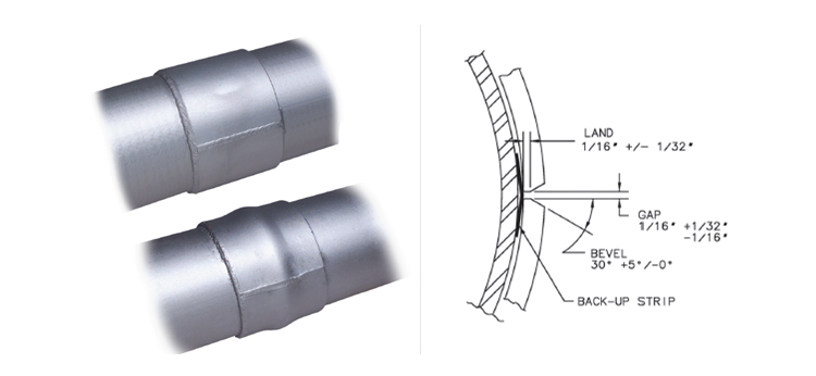
FIGURE-1: IMAGE SOURCE: TDW
- For structural support of dented/gouged pipe segment (ASTM A36 or ASTM A572 specifications)
- For strengthening defective girth welds (ASTM A36 or ASTM A572 specifications)
- For prevention of pipe bulging
- For padding and as pipe support (only one half is used)
Pressure Containing Sleeves (also referred to as Type-B sleeves)
Full encirclement sleeves for pressure containment, when designed and installed carefully, result in restoring repaired pipeline yield strength to original SMYS (Specified Minimum Yield Strength). Two sleeve halves are pressed and tightened around the damaged section of the pipeline and firmly held in place with the help of a pipe sleeve jack.
Welding involved only for joining longitudinal ends of two half-sleeves together (butt welding) for complete encirclement grip or longitudinal end of one half-sleeve to the pre-crimped back-up strip (fillet welding) of second half-sleeve. Circumferential welding is carried out as fillet weld with pipe metal and provides some support against longitudinal structural stresses. However, these sleeves have low capability to resist longitudinal stresses and, therefore, not suitable for repairing circumferential defects.
- For restoring MAOP of internal / external corroded pipe segment (ASTM A516, ASTM A537, API 5L PSL 1 & 2 specifications)
- For prevention or repair of leaks / spills (ASTM A516, ASTM A537, API 5L PSL 1 & 2 specifications)
- Can be used on leaking girth weld as full encirclement sleeve-on-sleeve welding configuration
- Contouring welded sleeves are also available for girth weld, flanges, and curved pipes.
Special Pressure Containing Sleeves
Special full encirclement sleeves are commercially available for ease in repairing leaking/spilling defects. These are pressure containing sleeves with a combination of bolting and welding. First, the sleeve is placed on leaking or spilling defect and tightened around the pipe with the help of nut-bolts to stop leakage.
These sleeves are provided with packing seals (longitudinal as well as circumferential), which helps prevent leakage before welding is carried out. Once the sleeve is proved in position for no leakage occurrence, both halves are longitudinally welded to each other and circumferentially welded to the repaired pipe. In the end, all the nuts are also seam welded to bolts and sleeve bodies to ensure durable pressure-tight repair.
Refer to Figure-2 for understanding the process.
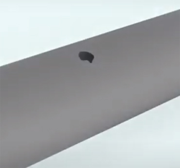
1. Leaking / Spilling damage
2. Sleeve placed on damaged pipe
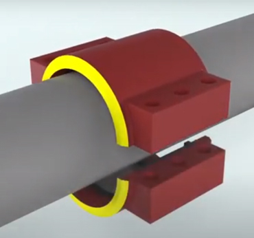
3. Sleeve bolted to stop leakage
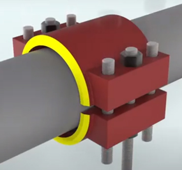
4. Finally bolted & welded repair sleeve
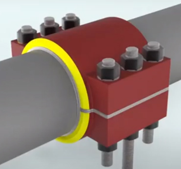
FIGURE-2: IMAGE SOURCE: PLIDCO
3.5 Composite Sleeves / Composite Wrap
Composite sleeves or full encirclement composite wraps are the latest innovation with regards to pipeline defect repair, where leakage or spill has not initiated. They are very advantageous for repairing contouring pipelines and those sections of pipelines that have fittings installed like small off-take or gauge points.
These are capable of restoring damaged pipelines to withstand original MAOP with the added advantage of providing pipe coating to guard against corrosion. Today, there are commercially available pre-fabricated sleeves (designed and cured in a factory for quick installation at the site) as well as wet sleeves wrapped and cured at site as per requirement.
Most popular and CPL approved (Chevron Pipeline Company approved) composite sleeve is “Clockspring” which are made up of corrosion-resistant high tensile fiberglass material. However, ASME B31.8 only accepts such repairs in case “proven through reliable engineering tests and analysis.” Where possible, composite sleeve wrapping is carried out at one-third of the operating pressure so that sleeve can share hoop stress once the pipe is restored to regular operation.
During application, fiberglass is wrapped around a damaged portion of bare pipe, after cleaning and/or grinding, in layers, and a filler metal is applied in each layer. For dented areas, special hardening filler material (provided by composite sleeve manufacturer) is used before the application of sleeve wrapping. Pipeline pressure should be kept reduced until the completion of sleeve installation and curing time.
Clockspring Sleeve installation process
Image Source: Ashtron Global Pte Ltd
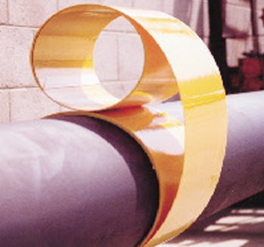
Composite sleeve installed
Image Source: TDW
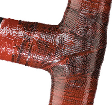
FIGURE-3: TYPICAL INSTALLATION OF CLOCKSPRING SLEEVE AND COMPOSITE WRAP
Installation of composite sleeves is never recommended for damaged pipes where cracks have initiated. Installation of composite sleeves should be done by personnel trained and certified by qualified instructors, preferably under the guidance of composite sleeve manufacturer. When such conditions are met, a composite sleeve offers damage repair for:
- External metal loss defects upt0 80% of pipe wall thickness
- External metal loss at bends and fittings
- External metal loss for girth welds with damage less than 50% of pipe wall thickness and damage width less than 30% of pipe circumference
- Are beneficial in arresting external corrosion of repaired pipeline segment
Important: Some pipeline experts/companies still doubt about the long-term integrity of composite sleeves due to the aging of sleeve material.
4. Off-Service/Decommissioned Pipeline Repair Techniques
Off-service or decommissioned pipeline repair techniques are mostly used for rectification of internal damage to pipelines. However, occasions arise when external damages can be cost-effectively repaired through partial decommissioning.
4.1 Insert Sleeves
Most of the internal defects arise in pipelines at girth weld as the remaining length of the pipe is often internally lined to guard against internal corrosion (especially when the pipeline is carrying corrosive fluids). To prevent internal damage in the vicinity of girth weld insert sleeves are used. These sleeves provide a cost-effective solution to internal corrosion as they are easy to transport and install at site.
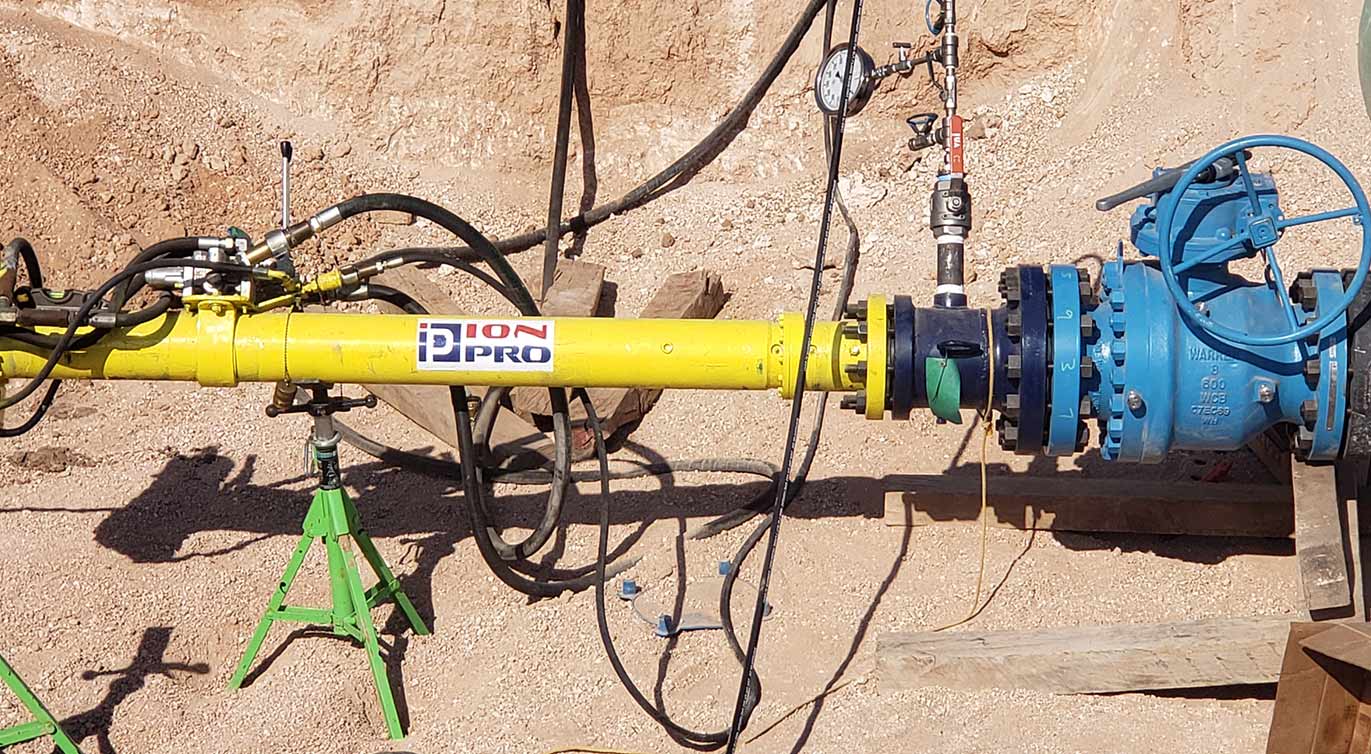
4.2 Hot Tapping / Line Stopping Operation
Some external defects require isolation of a damaged portion of the pipeline while keeping the remaining pipeline in continued operations. For such applications, Hot-Tapping is required upstream and downstream of the damaged portion to temporarily by-pass the damaged portion of the pipeline. Once the temporary by-pass pipeline is in operation, the damaged portion of the pipeline can be isolated and decommissioned using Line Stopping.
Line Stopping is an operation in which a damaged portion of the pipeline is isolated by welding Line Stopping-Split-Tees in close vicinity of the actual damage, upstream and downstream. Once welded and secured on the pipeline, stopple tees are used to insert Train Plugging Systems inside the pipeline (both upstream and downstream of the damaged pipe segment) to create an isolated pipe segment.
These train plugging systems provide “Double block and bleed” protection against any leakage/spillage of fluid into the isolated pipe segment. The isolated section is thus purged to be free of hydrocarbons. After additional purging of inert gas, any type of welded repair or cut-out operation can be done. Once the isolated segment is repaired and tested, train plugging system is retrieved, and pipeline flow is restored through the repaired segment.
5. Safety First
Pipelines are pressurized assets carrying hydrocarbons and pose fire hazards when welding/fabrication jobs are carried out on live pipelines. It is also well known that welders and fabricators are always in a hurry to complete the job. It is the responsibility of the site supervisor to ensure that:
- Job Safety Analysis (JSA) is carried out
- Follow Management of Change (MOC) process as per API RP 76
- Site workers wear proper PPE, and required consumables/equipment are available
- An authorized person has issued a permit to work before job initiation
- All job procedures are followed including LOTO (Lock-Out-Tag-Out) when required